Tuesday, May 31, 2011

Trike Done! Part 2

I mounted a water bottle cage on top of the main tube using t-nuts intended for wood working. I cut off the tangs, then set them into a hole drilled in the frame and welded around the edge. I actually found metric t-nuts at Ace Hardware where I seemed to go twice a week to pickup nuts and bolts.
Here's the boom clamp I made. I but a section of the 2" tube, then slit it and spread it out slightly. I cut a threaded nipple used for tensioning fence gates in half and welded the pieces onto one side for nuts. Then I welded on two bushings to hold the bolts. It turned out pretty nice.
Here's the rear deraileur - it came from the bike I snagged at Community Cycling Center.
Finally, we could start painting, and wouldn't you know we got a 70 degree day for it.
I was able to paint the entire bike all in one day since I could use the back yard and driveway.
Reassembly went pretty quick. This time, I replaced the temporary nuts with nylon self-locking nuts wherever I could, especially in the steering linkage. To adjust the steering, I first loaded the trike with 150 pounds of sandbags to simulate a rider.
Then I centered the middle link and adjusted in one wheel to match it.
Then I used a yard stick cut into two pieces to make a slide ruler. Two rings of inner tube hold the pieces together. I brought the other wheel in line adding .1" of toe-in. It tracks very nicely, so I'm happy with that.
I made a mount for the speedo sensor out of a prop rod from an old wire rack. I drilled a hole in the brake mount for a place to attach it. I wanted to put the wireless sensor on the rear wheel to minimize error, but the wireless wouldn't reach that far. It works here without any problems.
These are the steering bumpers - just a piece of old tire wrapped around the handle bar. The tire protects the seat frame.
I made a seat cover out of Pfifer Tex, an outdoor furniture material I bought at Fabric Depot. I hemmed all the edges 1" and popped in brass grommets then laced the seats on with 1/8" cord. I put on 2 and a half chains from Bad Monkey, and adjusted everything. Here are a few pictures of a really happy kid riding his new trike. We both rode in the Human Power Challenge this weekend. It's a great group, with a large contingent of homebuilders, and some of the fastest and most capable riders around here. He took home a medal, and I got some positive comments on both of the bikes. Good times.
Jack

Labels:

Trike Done!

My Bad - I haven't blogged in a while because I've been working feverishly to get the trike done before the Human Power Challenge which is put on by Oregon Human Powered Vehicles. Now that it's over and one, I'm catching my breath and tidying up the garage workspace as well as getting you caught up on the final part of the project.

I made handlebar mounts the same way I made the steering knuckles - by cutting pieces out of square tubing and welding up the seams. Then I cut up an old handlebar to make trike style direct steering bars. Somewhere I picked up a pair of bar-ends , which I'm using now as handles. Just by chance (not by design), swapping parts from side to side and front to back can give me 4 different hand locations/positions.
Here's the boom. The bottom bracket shell and shifter stem came from a road bike, but the sliding tube to fit into the frame is a 1 7/8" muffler pipe. Crude but cheap and it fits perfectly.
Here is #1 son testing the hand position to see if he can reach the full range when turning.

Now onto the drive train. I knew I'd need an idler to handle all that chain, so I started by turning a Raz'r wheel on the grinder and using a screwdriver to melt a groove in it. I made a spare while I was at it.
I laced string through the largest and smallest rings in the front and back and played around with the chain line by moving the idler around.
I ended up with this as the perfect location. The chain passes over the outrigger, and under the seat frame. With only 1/4" clearance above and below, I needed to be able to finely adjust the position of the idler.
This is the result. It mounts on a clamp around the short vertical tube that the rear triangle attaches to.And from the other side...I used links from an old chain for hinges on the clamp. It had to open up fully to go around the tube, then tighten down firmly with a bolt and welded-on nut.
more in the next post....

Labels:

Wednesday, March 16, 2011

More Wheel Pics

Here's a top view of the rear wheel installed. That's a 14-28 7 speed freewheel. We might swap that out for something with a higher range later on, but I had this one laying around and it's almost new.
Here is the left steering arm. The brake caliper mounts on top of the two towers. Yeah, I know, the spiral in the center of the brake rotors points the wrong way - the wheels are installed backwards, but that will get fixed when we take it apart again.
And the right is shown here. The caliper mounts underneath this one on similar towers.
Here is the right side again from underneath. The king pins are tilted in 20 deg, and back 15 deg. This setup gives me about 1.5" of trail and center point steering. I was shooting for a little less trail, but the bottom of the king pin prevents me from moving the axle farther forward. Another option would be to weld the steering arms to the bottom of the king pins, but I really want this to be easy to repair years from now.
I ordered some rod ends from McMaster-Carr to use in the steering linkage. At around $2.25 each, this was much better than trying to scrounge up a set of suitable rod ends like I did for my red bike. That only used 2, and it didn't mater what size they were. Here I need symmetry, so all 4 need to be the same (and I added a couple extra for future use since shipping was the same).

Jack

Labels:

Steering Arms

With the steering arms completed, #1 son was anxious to try painting them. Here, he's priming them.


The black semi-gloss we are using for everything that isn't going to be green is drying here.

Here are the wheels. The hubs and rims are black, with the green spokes. They look awesome in real life.

And here they are installed (temporarily). I put the back wheel on while my favorite son installed the steering arms and front wheels.

With the wheels bungy corded to prevent them from flipping back and bending the brake rotors, we can start laying out the seat. It will be non-adjustable, similar to the way a Catrike seat is hard-pointed to the frame.

Labels:

Saturday, March 12, 2011

Hubs Completed

Since the wheels for the front of the trike originally had coaster brakes, I needed to adapt them for a rotor. To make an adapter, I cut a donut from 1/8" thick steel, and drilled holes to match the rotors that I got as part of a complete kit from Bike Nashbar. I welded the donuts onto the hub flange that used to hold a sprocket.

I reused parts from the old wheels to build up the axles, then assembled them into the hubs.
Here's the outside of the completed wheel.
And the inside, or the brake side, of the wheel.
Jack

Labels:

Tuesday, March 08, 2011

Trike Steering Knuckles


Time to set up the front end. Keep in mind that this is the first time I've undertaken this, and I'm no pro. If you know a better way of doing this (short of learning a real cad/cam program), I'd love your input. I propped up the trike frame with a box and set the front tires in place. Shooting for about 1.5" of trail, I took a few pictures to refer to for alignment, and started fabricating the steering knuckles.

I started by cutting some tapered pieces to fit the tapered square of the "bottom brackets" that I'm using as king pins. these came from some 1.25" square tube scraps. I like working with this stuff because it's easy to cut and weld, and it's pretty strong.
Then I clamped the pieces onto the bottom bracket spindle (leaving room at the end to draw them up with the capture bolt, and welded up the joints.
With these parts completed, I used more square tube scraps and a few clamps to adjust the position of the pieces relative to each other in order to get the right angles for my steering and welded it all together. The idea here is to add everything that needs to be added, like brake mounts, and steering arms, then trim away everything extra. Crude but, hopefully, effective.
After drilling axle holes, I installed the wheels and built mounts for the disc brake calipers. Following a test fit on the trike, I added stud for the steering tie rod to connect to, on the wheel side of the trailing arm. To establish a wild stab at ackerman steering, I used a spreadsheet that I downloaded (in the links on the right of this page). The only real guess work was where in blazes to start my measurements from. In theory, one would measure everything from the king pin, but that goes out the window when the king pin is tilted aft and in to obtain center-point (or near to it) steering.

Again, I spent the better part of an afternoon looking at other trikes on the internet. I determined that some of the most respected trikes must be using the point where the tire meets the road as their reference point, so that's what I did. My steering arms will connect just inside and behind the brake rotors. Then I cut off all the extra material on my steering knuckles to lighten them up a little.

Labels:

Thursday, December 16, 2010

Trike Paint


My son gave the rims and hubs their first primer coat, to get ready for black paint. We picked out the paint scheme today. Glossy Meadow Green for the frame and semi-gloss Black for the accents. The rims and hubs will be black, and the spokes and nipples will be green.

Labels:

Hubs & Rims

Time to build some wheels for the trike. I'm combining two sets of bike wheels, taking the rear hub from both and placing them with the rims from one bike. The idea is to take advantage of the larger diameter axle, as well as use the cog mount as a brake disc mount. To do this, I disassembled the hubs completely, then welded the cog mounting piece onto the end of the hub housing. I discarded the brake shoes, return spring and middle bearing. The other two bearings are installed in the ends. I won't be using the cogs; they just indicate where the brake discs will go. I'll make some aluminum donuts to adapt the discs once I get them.


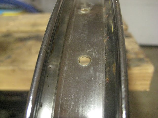
On to the rims... The front rim had only 20 spokes as opposed the rear rim's 28. So that I had a matching set, I welded up the 20 holes, then marked and drilled the rim for 28. It came out pretty good, I think.

Labels: